Description :
What is Transformer?
A transformer is a static electromagnetic conversion device. It transfers electrical power with one voltage ( step-up/step-down) from one electrical circuit to another separated electrical circuit with another voltage ( step-down/step-up).
The operating principle of transformer is based on Faraday’s Law of Electromagnetic Induction.
1. Electrical energy received by Primary winding in one circuit.
2. Then converted into Magnetic energy in magnetic circuit/core.
3. Magnetic energy is reconverted into Electrical energy in the secondary winding of another separate circuit.
Power Transformer:
It deals with bulk power ( say,30 MVA, 50 MVA, 100 MVA & above ), high voltage classes 132KV, 230KV, 33KV,66KV, 400KV, etc., and installed at the power station, transmission line/system, grid substations & other big substations. The efficiency of a power transformer is nearly 100% ( >99.5%) as it runs almost with a full load all day long. It may be step-up or step-down, at the power station step-up transformer – 11KV/132KV, 11 KV/230KV, etc is used whereas, in the transmission line/grid substation, both step-up & step-down power transformers are used as per requirement.
Why Transformer?
Power generating stations are situated far away from the consumer end for different reasons. Therefore long transmission lines are required to lead the electrical power to the distribution side. We know power is generated about at 11KV, if it is transmitted at this voltage, a huge amount of power will be lost (=I^2 R) in the transmission line & voltage will also be dropped (V=IR) in the line. If we want to reduce loss by increasing the size of the conductor (decreasing R ), the expenditure of the conductor & tower & fittings will be increased which is uneconomical. To decrease line current(I), transformers are used to step up voltage for transmission & at the end of transmission, voltage is step down for distribution purposes. Moreover, consumers are of different voltage classes, some are single phase 220 volts or 110 volts, some are 3 phase 440 volts, 11 kv or 33 kv, etc which also demand transformers of varieties size & voltage classes.
Principle of Operation :
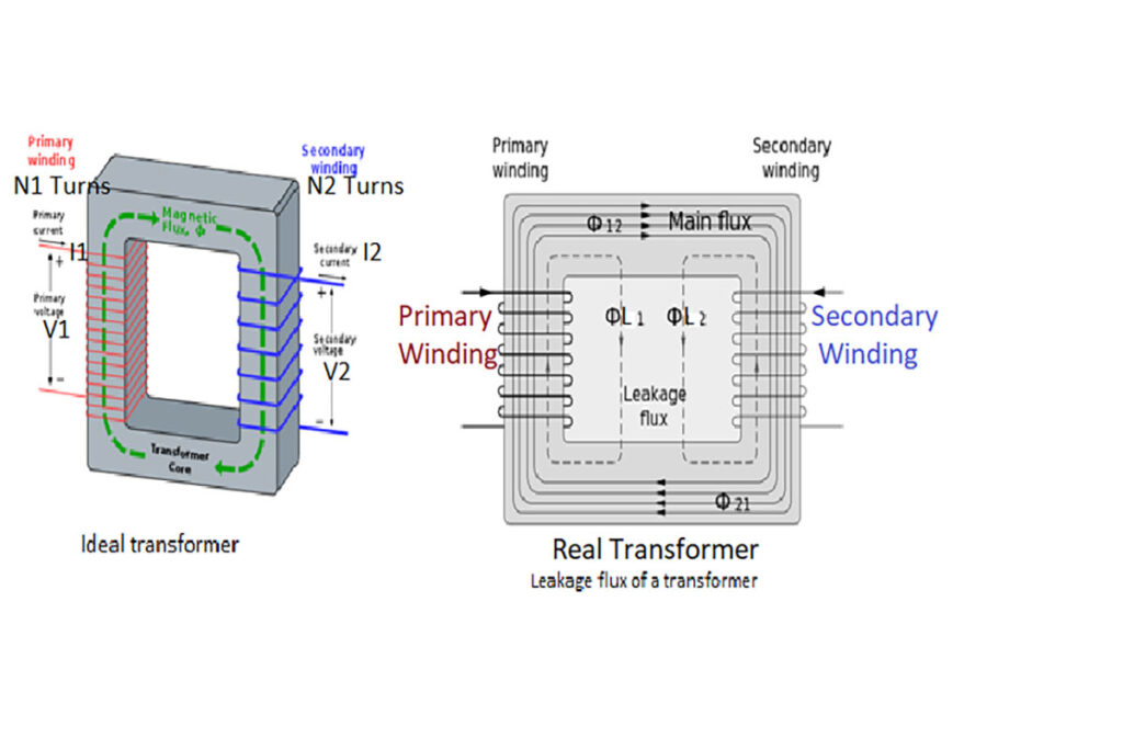
Fig above – shows the diagram of a single-phase transformer consisting of two windings – primary & secondary both are electrically isolated to each other & magnetic core is made of a laminated sheet of iron. Primary & secondary windings surround the limbs of the core but are insulated from the core. Electrical energy received by primary winding at voltage V1 is converted into magnetic energy in the core & a magnetic flux φ is produced.Majority part of φ flows through the magnetic circuit as the permeability of iron core is about 900 times higher than that of air. A small portion of the produced flux (φL1) flows through the air which does not link with the secondary winding. The majority part of the produced flux (φ12 ) that links with the secondary winding induces a secondary voltage,V2. Thus magnetic energy is reconverted into electrical energy into the secondary circuit. Flux φL1 which is called leakage flux does not contribute to induce voltage in the secondary winding as it only passes through the air. If the load is inserted into the secondary circuit, circuit/load current will flow through the closed circuit.
Ideal Transformer, EMF Equation & Transformation Law :
An ideal transformer has
1. Zero winding resistance 2. No leakage flux
3. Infinite Permeability & 4. Zero core loss.
EMF Equation ( Faraday’s Law)
Lets,
Primary current = I1 ,Primary winding turns= N1 , induce voltage at primary winding = e1,
Secondary current = I2 , Secondary winding turns= N2 , induce voltage at secondary winding = e2
e1=N1(dφ/dt) where φ = φp sin(ωt)
= N1 ωφp cos(ωt)
=6.2832 fφpN1 cos(ωt)
So, from the above equation E1=4.44fφpN1, similarly E2=4.44fφpN2
So, E1/E2=N1/N2 ———- (1)
Primary Amp-Turn (I1*N1)= Secondary Amp-Turn(I2*N2) ———- (2)
Transformation Law :
From equation (1) & (2) , E1/E2=N1/N2=I2/I1
Why Transformer rating is in KVA/MVA not kW/MW ?
Copper losses (I²R) depends on current which passing through transformer winding while Iron losses or core losses depends on Voltage. These losses are independent of the power factor at which the transformer operate.
Total losses depends on voltage (V) and current (I) which expressed in Volt ampere (VA) and That’s why the transformer rating is expressed in VA or kVA, not in W or kW.